SWAP-IT Execution Engine
The Execution Engine is a software component for the execution of processes, which was developed as part of the Fraunhofer lighthouse project SWAP-IT. Further information about the SWAP-IT software modules can be found within the SWAP-IT Demonstration Scenario.
The Execution Engine itself is an OPC UA server and can be seen as interface between a scheduler and resources on a shop floor, which is able to execute scheduled processes and in this context, integrate custom Resource Assignment strategies, be attached to custom schedulers and map process parameters. Figure 1 illustrates the functional blocks of an Execution Engine and more details about its operational logic can be found in the section Execution Engine Logic. The Execution Engine Data Object constitutes a data base that holds all parameters, specified within a process description. Here, the Execution Engine Data Object receives resource parameterization from the scheduler and stores them for the execution of Services. Besides, the Execution Engine Data Object receives service results from the resources on the shop floor, which are then used to either update existing variables within the Execution Engine Data Object, or to add new variables to it, which can later be used for a parameterization of a Service.
To effectively find resources on the shop floor and assign services to them, the Execution Engine interacts with a Device Registry and can integrate custom Resource Assignment strategies. To execute Services on the Shop Floor, the Execution Engine has a build-in Control Interface, which features an arbitrary number of OPC UA Clients that interact with the resources on the Shop Floor.
Besides, the Execution Engine can integrate custom schedulers through its Dispatcher Interface. Here the Execution Engine provides a set of Dispatcher Callbacks to react to scheduled Tasks and Services. In addition, the Dispatcher Interface provides a callback to communicate the completion of a Service Execution to the scheduler, as well as a callback to provide process data to the scheduler. These data can then be used by the scheduler to e.g., evaluate constructs such as loops or conditions.
As default implementation, we connect the PFDL Scheduler to the execution engine to run it in the SWAP-IT context. However, the Execution Engine provides an API to connect the Execution Engine to Custom Dispatcher Integration.
A small example on how to run the Execution Engine can be found in section Getting Started.
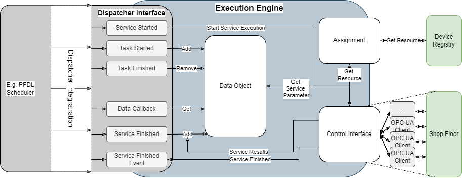
Figure 1: Components of an Execution Engine
Tasks and Services
In general, the Execution Engine distinguishes two constructs during process executions: Tasks and Service. In this context, a Service is the execution of a single functionality, e.g., a production skill, that the Execution Engine executes on another entity on a shop floor. In contrast, Tasks are construct that are build around services to enable the definition of process sequences. Here, tasks are only executed in the context of a Execution Engine. Tasks can be nested and can contain other tasks, as well as services, so that with both, tasks and Service, arbitrary process sequences can be specified and executed. In this context, Services can only be related to each other sequentially within a Task, but Task can also be executed in parallel to each other.
Figure 2 gives a short overview of the interplay between Tasks and Services. The illustrated process features a Milling Service (1) and two paintingTasks (2) that are executed in parallel. Within each paintingTask, a Painting Service (3) is executed and after the paintingTasks are completed, a Drying Service (4) is executed. The right side of Figure 2 shows a visualization of the process as a petri net, which outlines the difference between Tasks and Services. Here, each Service in a process execution requires the placing of a token by a resource, which previously executed the service. This token is provided by the Service Finished Event (Figure 1) callback of the Execution Engine. In contrast, Tasks do not require external tokens, but instead, are executed around services, to e.g., coordinate the execution of Services.
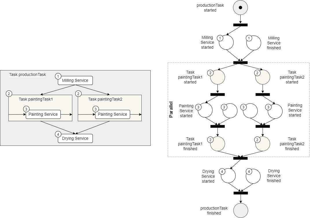
Figure 2: Example Process consisting of Tasks and Services
Shop Floor
The Control Interface of the Execution Engine interacts with entities of a shop floor to execute Services. Here, the Control Interface’s OPC UA Clients need a standardized interface to the shop floor entities. This interface is based on the Common Information Model , so that an Execution Engine can interact with each OPC UA Server that includes information models based on the Common Information Model.
Device Registry
The Device Registry is another software component of the SWAP-IT Architecture that makes shop floor resources available to process executions. In this context, OPC UA Server, representing entities of a shop floor, can register themself in a Device Registry. During its Resource Assignment, the execution engine can request available resources for a specific Service from the Device Registry and then deploy an assignment strategy to assign the Service to one concrete resource. In this context, Device Registry also includes a built-in functionality for filtering resources based on their capabilities. For example, this filtering can be used to assign a transport task to an autonomous guided vehicle (AGV) with a maximum payload restriction. The Execution Engine can now use the Device Registry’s Filter Agent Method to obtain a list of AGVs that can carry a specific product. Factors such as the product’s weight and the maximum payload restriction of the resources are also considered by the Device Registry to filter and identify suitable resources.
Production Flow Description Language and PFDL-Scheduler
The Production Flow Description Language (PFDL) is a powerful tool used in the realm of manufacturing and production management. It serves as a standardized language for describing and documenting the various steps and processes involved in manufacturing a product. A PFDL program corresponds to a single ordered product and specifies the production steps involved. It also serves as an input for an order controlled production, which can process it automatically. A PFDL program consists of structs and tasks, allowing for the definition of runtime aspects such as loops, conditions, and synchronization.
PFDL offers a structured and systematic approach to defining the production flow. It allows manufacturers to break down the entire production process into individual tasks and sequences, providing a clear and comprehensive representation of how the product is made. Within a PFDL program, manufacturers can define different aspects of the production flow such as task dependencies, parallel execution, loops, conditions, and synchronization. This flexibility enables the creation of complex and dynamic production flows that accurately reflect real-world manufacturing scenarios. Overall, PFDL plays a crucial role in enhancing the understanding, communication, and automation of manufacturing processes, ultimately leading to improved productivity, quality, and efficiency in the production environment.
PFDL Scheduler
The PFDL itself is just the description language and needs to be parsed, validated, and transformed into a structure to control the production process. All of these functionalities is done by the so-called PFDL Scheduler. The scheduler parses and validates PFDL files, which are then transformed into a domain model, which is a representation of the production order as a python object. This model can then be used to generate a petri net, which is used to control the production by triggering events and receive events, e.g. when a service has finished. To enable this, the PFDL provides interfaces in both directions enabling a process control that makes use of generated PFDLs and keep track of the current state of the execution.